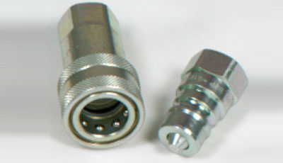
DIN-series-couplings
BSP SERIES
| DN | Size | Thread Type | Specifications | ||||||||
| LP | LS | S1 | S2 | Dia D | L | Dia C | Max Operating Pr | Minimum Brust Pr | |||
| 6.3 | 1/4" | 1/4" BSP | 36 | 53 | 22 | 19 | 27 | 72 | 14.2 | 350 | 1000 |
| 10 | 3/8" | 3/8" BSP | 40 | 61 | 27 | 24 | 35 | 81 | 18.95 | 300 | 1000 |
| 12.5 | 1/2" | 1/2" BSP | 46 | 63 | 30 | 27 | 38 | 87.5 | 20.56 | 300 | 1000 |
| 20 | 3/4" | 3/4" BSP | 56 | 85 | 38 | 36 | 48 | 112 | 27.95 | 250 | 640 |
| 25 | 1" | 1" BSP | 63 | 96 | 46 | 41 | 55 | 126 | 31.3 | 220 | 400 |
Note : All dimensions are in mm, unless otherwise specified. Pressure in bar.
These dimensions are for reference only and are subject to change as per design modifications.
In comparison to ISO.B couplings, ISO.A are :
- Connection System: By pulling back the sleeve.
- Disconnection System: By pulling back the sleeve.
- Shut-off System: Poppet Valve
- Connectable: without Pressure
- Materials:
Body: Carbon Steel-EN1A/EN8DM
Springs: Spring Steel as per IS:4454 Grade II
Balls: AISI E-52100 Grade 100
Seals: NBR (Nitrile) Temprature Range -30° to 100°C
Backup Ring: PTFE - Surface Treatment: Zinc Plating with Cr III based Passivation.
FLOW RATE CHART
| Size | 1/4" | 3/8" | 1/2" | 3/4" | 1 |
| Flow Rate (Ipm) @ 2 bar Pressure Drop | 15 | 50 | 75 | 150 | 230 |
